Showing posts with label 10M45S. Show all posts

Tuesday, December 25, 2007

how little ripple is enough?


0.002vac is the resultant ripple at my preamp after the second 10M45S chip. at B+, it was 0.009vac, and between the two 10M45S, it was 0.008vac.

Seems like one chip alone is not enough. Two together resulted in around 77% drop in ripple in my high voltage supply to my preamp.

I guess 0.002vac is good enough?

The measurements can be seen here.

Monday, December 3, 2007

mods to 5687 preamp


finally the feedforward shunt regulator design taken from John Broskie's blog is incorporated into the 5687 preamp.

it is now providing dc with minimal noise to the circuit, biasing the tubes at 22.2mA per tube.

will try to post a hand-drawn circuit of the implemented circuit later.

more pics here.

Saturday, October 27, 2007

Feedforward Shunt Regulator again


I redid the Shunt Regulator again. One channel seem to "runaway" when switched on for a while. This caused some speaker cone movements even when no source is playing.

Measuring the incoming supply, the voltage between the two 10M45S, and the output voltage, it seems that only one of the chip is giving this problem. Looks like the small heatsinks are not enough to dissipate the heat, resulting in thermal runaway... i think this what it is called.

So, i did it using plain old point to point wiring on a spare heatsink that i have. This new version will be muncho mancho enough to take the heat, else nothing would. ;)

During testing, the voltage did not fluctuate much. No runaway this time. Cathode resistors measured spot on at around 2.98v. The 10M45S are sourcing around 10mA per chip as per specification. It's just that the 10% coffin resistors are not accurate enough to produce equi-voltage between L and R. I may have to measure for a pair that fits the bill.

Maybe I should start digging for my 2k2 vishay power resistor somewhere in my box...

Saturday, October 13, 2007

John Broskie's B+ feedforward shunt regulator


i've actually got this board done up before i shifted. that must have been 3 or 4 weeks ago. i was even comtemplating putting it into my 5687 preamp the day before NoiSing07 so that i can demo the preamp with the regulator.

good thing that i did not... it took many attempts before i got it to work. most of the time, i burnt resistors as i forgot where the ground of the board is cos it was sooo long and i did not mark the board with symbols.

i also killed quite a couple of 10M45S chips. it seems that even though it is sourcing 10mA, heatsinks are still required on the chips.

it seems that the regulator added a sense of scale and resolution to my soundstage. it is easy to pick out details... very resolving. also, the bass seems to have benefitted by being more controlled and detailed. not quite sure how to put it, but i would say that this is worth the effort.

perhaps other HV regulator designs would produce the same effect?

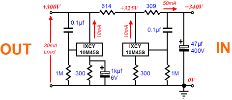
the circuit is based on Jon's feedforward shunt regulator.

parts are swapped below as mentioned:
1. first dropping resistor after B+ as 1k2 10W instead of 309R
2. second dropping resistor after B+ as 2k2 10W instead of 614R
3. B+ is 290V, between dropping resistors is 228V and 136V (L channel)/140V (R channel)